A multimeter is one of the most useful tools in an RV or campervan toolkit.
When installing a campervan electrical system, you’ll use the handy tool all the time. You’ll test your solar panel’s output, battery levels, cable continuity, and much more.
Even once your van conversion is complete, the multimeter is the first tool to reach for when you experience electrical problems on the road.
Most of our electrical articles and all our installation posts refer to a multimeter. We figured it’s about time we explain more about this indispensable tool.
This post explains what you can use a multimeter for, why we consider it a compulsory bit of kit, and how to use it.
We’ll go through where to put multimeter leads when taking measurements, what settings to use and what to look for when buying one.
Everything you need to know about campervan electrics. Now available in ebook and paperback!
Learn how to design, size, install and troubleshoot your camper’s electrical system.
What is a Multimeter?
A multimeter is a battery-operated, handheld device capable of taking multiple electrical measurements, hence its name.
Modern digital multimeters measure voltage, resistance, and other values well beyond most RVers and campervan owners’ needs.
You’ll find a multimeter in every electrician’s toolkit, but with minimal ‘training,’ a novice can take some measurements safely too.
Why You Need a Multimeter in Your RV Toolkit
Campervan electrical problems aren’t great, but they are par for the course.
Appliances can break down; components can develop faults, and batteries can seem to drain fast.
A camper has hundreds of metres of wire and dozens of appliances and components in its electrical design. When something goes wrong, it could be a troubleshooting minefield.
You need a tool to pinpoint where the problem lies in the system and help identify the cause.
A multimeter is a tool for the job. Without it, the only safe way to diagnose problems is to call in an electrician – who will bring their own multimeter with them.
When installing any aspect of campervan electrics, you’ll use a multimeter every step of the way. Make sure to include one in your camper’s toolkit.
8 Ways to Use a Multimeter in a Campervan
There are loads of ways a multimeter comes in handy when living in a van.
Here are some common uses, all helpful for diagnosing electrical problems.
- Check if a campground’s pedestal is working. If you’ve hooked up, but the battery bank isn’t charging, use the multimeter to check if the outlet provides any voltage.
- Confirm what voltage a campground’s hookup is supplying. Some countries supply both 110v or 240v, and you need to use the appropriate voltage for your setup.
- Find a blown fuse by measuring its resistance.
- Using a multimeter volt reading is useful to see if the fuse is blown without removing it to check visibly.
- Check battery voltage to indicate its charging state.
- Identify broken or damaged wires by measuring circuit continuity.
- Confirm that the inverter is outputting the correct AC voltage.
- Check an appliance’s supply voltage to help identify a problem.
Without a multimeter, it is difficult to troubleshoot electrical problems.
When you click on links to various merchants on this site and make a purchase, this can result in this site earning a commission. As Amazon Associates, we earn from qualifying purchases. For more info, please check our disclosure page.
Safety Warning
Electricity has the potential to cause severe injury or death to you and significant damage to your van.
Leaving installation and troubleshooting to the professionals is a good idea if you don’t know what you’re doing, but at least understanding the basics will help you keep safe.
Learn more about electrical basics for campervans by reading our post on campervan wiring.
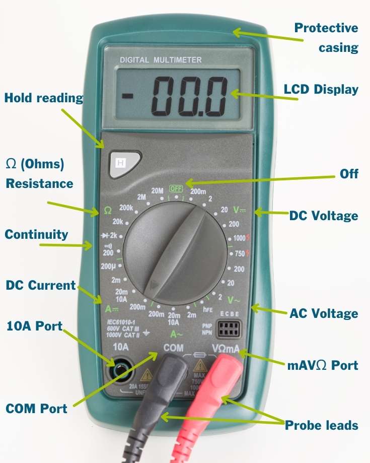
The Anatomy of a Digital Multimeter
Modern multimeters come in a variety of colors and shapes. While some have extra buttons and features, they all have the same basic parts:
- An LCD screen to display measurements
- One black and one red probe to take the measurements
- Three ports to connect the probes
- A selection dial for choosing electrical scales and the measurement being taken
Probes
Most multimeters include a pair of standard probes. They’ve always served us well, but other types are available, like alligator clips or tweezers.
We’ve never needed extra probes, but it’s good to know you can replace them should you ever need to.
Remember, damaged probes could cause serious harm, and they’re only a few dollars to replace. Never use a damaged probe!
Ports
The three ports are distinctively labeled:
- COM stands for common and is used to connect the black probe. It’s the reference point for the circuit’s earth or ground.
- mAVΩ is used to connect the red probe when measuring voltage, resistance, and continuity.
- 10A port is used to connect the red probe when measuring currents up to 10 amps. It has limited use in a campervan or RV.
Settings on a Multimeter & What They Mean
The selection dial adjusts the multimeter’s circuitry resistance to read voltage, current, or resistance.
There are symbols on the dial. Some are unusual, so here’s an explanation of what each means:
V∽ – AC voltage
V ⎓ – DC voltage
Ω – ohms
A – amps
μ – one millionth (or micro)
m – one thousandth
k – one thousand
M – one million
There are numbers around the dial too. Use these to select the measurement scale. The sections below cover how to decide which scale to use, so don’t worry.
Here are some general hints and tips about using the device that apply to all situations. We’ll cover how to take each measurement below.
- Plug the black probe into the COM port.
- Plug the red probe into the mAVΩ port.
- Connect the red probe to the positive side of the circuit; the black to the negative or ground. If you’ve done it the other way around, the reading will be -ve.
- Don’t touch the business end of the probes when they’re connected to anything. Always keep your fingers on the plastic handles to avoid nasty shocks.
- Do not allow the probe tips to contact one another when taking measurements on live terminals. It will interfere with any measurements.
- Position the multimeter so you can see the display screen from your measuring position. It sounds easy enough, but it’s not always so simple when you’re rolling around on a tiny van floor. There’s usually a retractable stand on the back panel.
- Set the expected scale before taking any measurements.
- Don’t forget to switch it off when you’ve finished, so the batteries don’t flatten. If you don’t use it often, remove the battery between uses.
- Store it somewhere safe and protected from being knocked about and damaged when driving.
- Read the multimeter instruction book for information about the display screen and how the readings or errors are presented.
How to Use a Multimeter to Test DC Voltage
Measuring voltage is one of the most common uses for a multimeter in a conversion project and troubleshooting electrical problems in your campervan.
If an appliance or component isn’t working as you expect, the first question you’d ask is if it’s getting any power. You check this by measuring voltage (after making sure it’s switched on).
A multimeter works by measuring the difference in voltage between two points.
- Plug the black probe into the COM port
- Plug the red probe into the mAVΩ port
- Determine what voltage you expect on the circuit*
- Turn the dial to V ⎓ and the number higher than the expected voltage**
- If you need to position the multimeter so you can use it handsfree, prop it up now
- Connect the probes to the circuit. You may need to apply light pressure to get an adequate contact
- Read the measurement from the LCD screen***
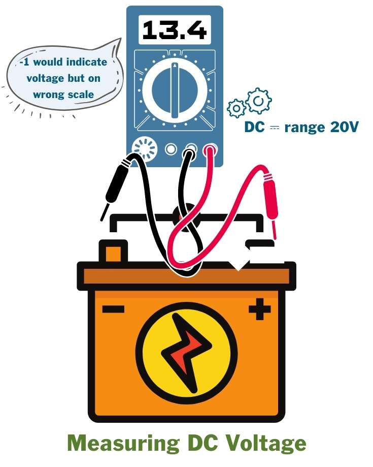
* Most campervans and RVs have a 12v DC system, so in this case, you’d expect to see approx 12v. Some vans have 24v or, rarer, 48v.
** In a 12v system, set the dial to 20v.
*** If the meter reads 1, you’ve probably selected a range too low for the measured voltage. Increase the voltage range on the dial.
Use the multimeter to test DC voltage at different points of a circuit to help with troubleshooting. Here are a few examples:
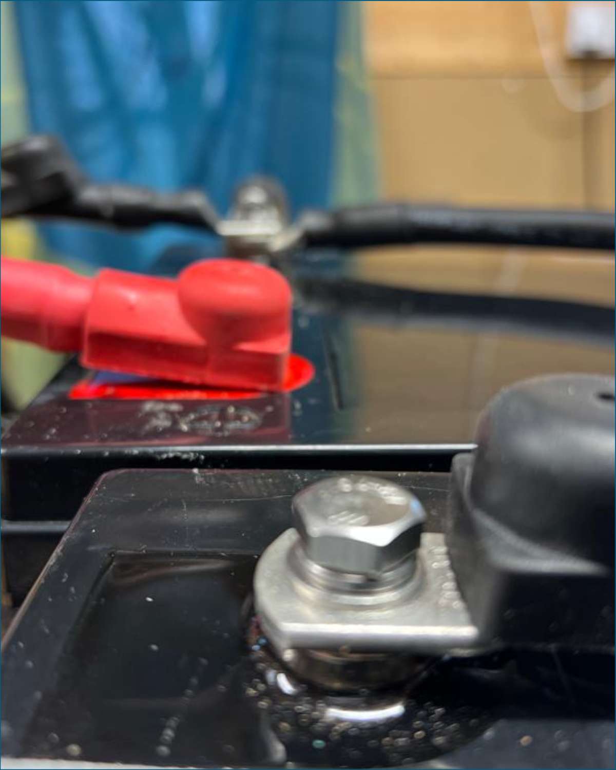
Test a battery’s voltage to indicate its charge level. Connect the black probe to the -ve terminal and the red probe to the +ve terminal. Read our post on campervan batteries for information on charging profiles and expected voltage.
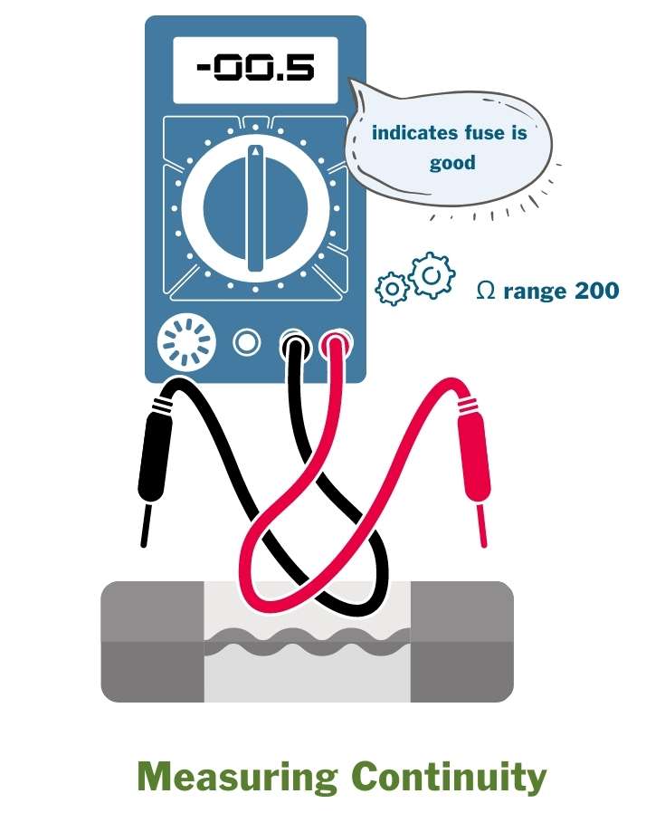
Test a fuse in situ to check if it’s blown. Connect the probes to the two visible test points on the fuse. It doesn’t matter which is red and which is black.
Use the multimeter to measure any voltage drop across the fuse. A reading of zero indicates no voltage difference, so the fuse is good.
Test a switch is functioning correctly. With the switch in the off position, connect the black probe to an earth point and the red to the positive input wire. If there’s no fault between the battery and the switch, the reading will be close to the battery voltage.
Now close the switch to the on position. With the black probe still connected to the earth point, test the output wire from the switch. The readings should match if the switch is working.
Checking Continuity with a Multimeter
Checking continuity is the other most common use for a multimeter in a DIY campervan conversion project.
As the name suggests, it tests if there’s a path for electricity to flow from one point to another. The multimeter sends a tiny current between the two probes.
If the circuit is intact, the multimeter will display a tiny reading (it’s a tiny current).
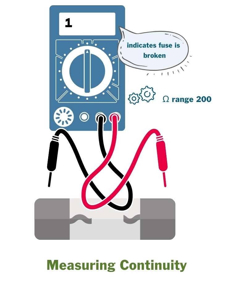
Otherwise, the reading will display an error, depending on the multimeter model, indicating a break in the circuit between the two tested points.
During a conversion and when installing any electrical components, you’ll use continuity testing a lot to test each part of the installation.
- Switch off any power to the circuit you’re testing*
- Plug the black probe into the COM port
- Plug the red probe into the mAVΩ port
- Set the dial to continuity test**
- Connect the probes together to confirm that the meter is working. You should see a small read-out.
- Connect the probes to each point you want to check continuity between
- Read the measurement from the LCD screen***
* In a campervan, either remove the circuit’s fuse or switch off the entire supply at the battery isolator switch.
** If there is no continuity between the 2 points, the reading will display an error depending on the multimeter model. If there is continuity, the meter will display a reading.
The reading doesn’t matter when only testing for continuity. We’ll cover this more in the next section about measuring resistance.
*** Some models of multimeters emit an audible beep when continuity is confirmed.
Measuring Resistance with a Multimeter
Voltage drops, without the loss of continuity, might indicate increased resistance on a circuit.
As with checking continuity, the multimeter sends a tiny current between the two probes. This time it measures its resistance, rather than merely checking that the circuit is intact.
Let’s say your 12v fridge isn’t working correctly. You’ve measured the voltage on the circuit, and it’s lower than you expected. The fact that there’s voltage confirms there’s continuity, but why is the voltage low? You’ve measured the battery voltage, and it’s hovering around 12.4v, so it should be ok.
It is a perfect example of when to measure resistance along each part of the circuit.
- Switch off any power to the circuit you’re testing*
- Plug the black probe into the COM port
- Plug the red probe into the mAVΩ port
- Set the dial to the Ω setting and choose the lowest resistance value
- Connect the probes together to confirm that the meter is working. You should see a small read-out.
- Connect the probes to each point you want to measure continuity between
- Read the measurement from the LCD screen**
* In a campervan, either remove the circuit’s fuse or switch off the entire supply at the battery isolator switch.
** Resistance measurements over 1 Ohm ( Ω ) are generally an indication of a problem with the circuit wiring.
A larger reading might also be because other components are still in the circuit, or connected via parallel circuits. You may need to disconnect them to remove their impact.
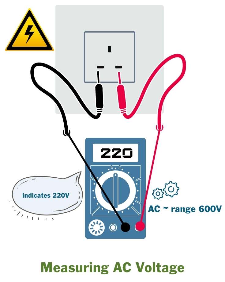
How to Measure AC Voltage with a Multimeter
This article does not replace the expertise of a qualified electrician.
It only provides information about how to measure AC voltage with a multimeter. You will be working with live voltages high enough to kill you.
If you need to do fault-finding on AC circuits, we recommend you use a qualified electrician.
Some RVs and campers use AC power to recharge the leisure battery bank from a shore power hookup, and run appliances through an inverter or directly on the AC circuit when connected to the main supply.
You can use a multimeter to measure AC voltage to:
- check if a campground pedestal is working and, if so, what voltage it’s providing
- measure what voltage is at a suspected faulty socket
- check if the inverter is outputting the correct voltage
In each case, use a multimeter to measure the voltage at the socket.
- Plug the black probe into the COM port
- Plug the red probe into the mAVΩ port
- Set the dial to V∽ and choose the relevant voltage setting*
- Insert the probes into each live terminal**
- Read the measurement from the LCD screen
* The multimeter dial has two AC settings: 200 and 600 volts (or similar depending on the model). If your camper uses 110-130v, select the 200v setting; for campers on 220-240v, select 600v.
** If you do not understand this, don’t touch it and get a qualified electrician to help you. You may need to negotiate socket safety devices to insert the probes to get good contact on the live terminals.
Graham Bogie

Graham is a seasoned marine electrical engineer with two decades of experience designing customized electrical systems for plant machinery and converting campers and overland vehicles. His expertise has led him to author the reputable Campervan Electrics Handbook and become the chief designer of the RV Wiring Design Tool. As a knowledgeable figure in the field, his YouTube channel, blog, Facebook group, and newsletter, offering electrical advice and product reviews, reach more than a million users each year.