This is the ultimate guide to campervan wiring. With this guide, you can wire your camper like a pro. You’ll have everything you need to know about campervan wiring, from the basics all the way up to more advanced concepts. Ready?
A campervan electrical system is a lifeline to van living. With the proper setup, off-grid living can become a reality.
The need to recharge batteries at expensive campsites dwindles. You can wild camp and boondock, taking advantage of glorious views, and still chill a beer or two.
Undertaking a DIY camper van conversion project is quite a challenge. The electrical system is probably the most significant and complex task of all.
It isn’t just about getting suitable batteries and fitting a few solar panels on your roof. It’s the beating heart of your lifestyle.
The first step is figuring out exactly how you’ll charge your batteries and buying your campervan appliances. But then it’s time to get it all installed and whirring.
But how does it all go together?
Understanding the components of a campervan electrical system is critical to a safe installation. And all that knowledge will help with future maintenance and troubleshooting when you run into problems on the road.
This post is the complete guide to every aspect of campervan wiring. We’ll start with the basics, explaining each component, why you need it, and how to choose the right one.
We’ll discuss wiring in detail, including calculating wire sizes and tips for installing cable runs.
We end with a step-by-step guide on how to wire your campervan electrical system. Plus, we’ve provided a definitive list of the tools, resources, and materials you need for the job.
An Introduction To Our Campervan Wiring Guide
A camper’s electrical system is fundamentally made up of three core components:
- The supply side is how we generate electricity – solar panels, shore hookup, a generator, and the camper’s alternator,
- The battery bank is how we store the electricity generated so we can use it later, and
- The load side comprises various AC and/or DC circuits and how we use the electricity generated and/or stored in the battery bank.
You don’t need to install every method of generating electricity in your camper. For example, some people only have a small solar panel.
Others have massive solar arrays and can charge the battery from their engine and generator.
You can charge the battery from a mains supply. Some conversions include AC circuits that run from the mains, bypassing the battery bank altogether.
In this post, it would become unwieldy if we included how to wire every aspect of a system’s supply, battery, and load.
Instead, we have separate articles on how to wire the supply side and the battery bank:
- Solar panels
- Shore power
- Generators
- Transfer Switches
- B2B Chargers
- Split Charge Relays
- Campervan Batteries
This article focuses solely on wiring a 12v campervan electrical system from the battery to the appliances.
The rest of the article is in-depth, so we’ve numbered each heading to help keep you on track.
1. When To Start Your Campervan Wiring
Camper van conversions are big projects, so at what stage of the build should you start the electrical installation?
If you have the luxury of starting a van conversion from scratch, you can plan every aspect of your build while stripping it out.
You will likely want to hide the wiring behind walls, lining, and furniture. Some of the last components to install in the conversion are electrical appliances such as reading lights and fridges.
So, because the electrical part of the build will start early and finish late, having well-thought-out plans is key to avoiding re-work. It will also ensure easy access to the electrical looms throughout the build.
Here are our top tips for getting started with the wiring:
- Have a detailed list of every electrical appliance, device, and socket you want to install.
- Detail exactly where they’ll be physically located in the completed build. Don’t forget to include where you’ll install the batteries, fuse blocks, switch panels, bus bars, and earth point.
- Pay careful attention to your cable runs. We’ll cover this in more detail further into the article, but aim for the shortest cable runs for each circuit. You may need to compromise on the design when trying to get the shortest runs.
- Always aim to keep your cable runs inside the van. Any cables outside the van could be damaged by road debris, insulation might get broken, and any water ingress may cause cable corrosion. It also makes fault finding more difficult.
- Consider standardising your cable sizes and connectors. Go up a higher current rating rather than a lower one wherever possible.
- Cable is sold in long lengths. Cable drums are often 100m+. It’s usually more cost-effective to buy and use a larger wire than every exact size.
- We opted for 3 sizes in our van conversion (small – 2.5mm², medium – 6mm², and large – 70mm²), covering all bases.
- Preferably lay all your cables before laying floors or insulation – they don’t need to be connected at either end. But number cables so you know what they are later.
- You can lay cables before installing the components, ready for connecting at the right time in your build.
- Leave enough extra cable for contingency. It’s much easier to trim excess cable later than rerun the cable.
- Begin by installing common components like the fuse blocks, bus bars, and switch panels early on.
- Tag the end of every cable with a number. It will help you remember what each is for later in the build.
2. Skills, Support, Tools & Components Needed
If you’re reading this, you’re probably thinking about installing your campervan electrics yourself. It’s certainly possible, and you need a few things to get started.
2.1. Skills
You need a few skills to install your camper’s wiring or be willing to learn them along the way.
- Basic understanding of electrics
- Hands-on DIY skills
- Familiarity with troubleshooting electrical problems
- A solid understanding of how to use a digital multimeter
2.1.1. Understanding of 12v Electrics
Reading this article is an excellent start if you’re a beginner, but it only takes you so far. Handling electricity has inherent risks, so knowing how to handle it safely is crucial for your safety and that of your van and its occupants.
There’s a lot of information available on the internet about how it all works. You could spend your evenings checking all the opinions out there. Or you can buy our book (shameless plug).
It covers every aspect of your campervan electrical system, from wires to solar panels to battery banks. It’s available in print, pdf, and epub.
Use discount code Mowgli10 for 10% off the electronic versions
Even if you want to outsource the installation, learning some basic electrical skills to be self-reliant when you’re on the road is a great idea.
Things break occasionally, and these skills will ensure you’re in an excellent position to troubleshoot the problem, if not fix it.
2.2. Support
Even armed with in-depth knowledge, there are undoubtedly times when you need to reach out for a little extra support and guidance.
Perhaps you feel you’re not getting enough power from your solar panels and want some expert advice. Or you’re uncertain how to wire in a relay for your water heater. Or you just need reassurance that you’re about to put the correct wire in the correct place.
There are several Facebook groups dedicated to campervan conversions. Here are a few we’ve always found helpful and recommend you join for community support:
- The Campervan Electrics Handbook Facebook group (hosted by our very own Graham!)
- Campervan Electrics
- Campervan Conversion
There are many others, though we prefer to avoid the groups with hundreds of thousands of members. They’re more likely to attract useless, judgemental comments from the handful of tw*ts that ruin these otherwise helpful forums.
2.3. Tools
You’ll need a few tools to wire a campervan. Having the proper tools will make the task at hand far easier. You may have some in your toolkit already.
- Multimeter checks wire continuity, connections, and electrical values,
- Megga earth tester (nice to have) to confirm earth insulation (silly expensive though),
- Wire cutter/stripper to prepare wires correctly,
- Soldering iron for joining and repairing wire connections,
- Heat gun to reduce and seal wire heat shrink to protect wires,
- Crimping tool to correctly secure terminals to the wire ends,
- Selection of metal cutting drill bits to make way for cables and securing components,
- Pliers are multipurpose tools to grip, bend, and hold “stuff,”
- A selection of screwdrivers and spanners to open, secure, and fix a range of “stuff,”
- Hacksaw to cut large cable,
- Campervan wiring diagram – you need a plan to work too.
2.4. Components
The definitive list of components needed to wire a camper varies depending on your detailed electrical design. However, here is a list of the most common components needed to wire a 12v system.
How many of each you need depends on your setup. Don’t be discouraged if you don’t know each of these components or why you need them; we’ll cover that in the next section.
- Cable ties
- Conduit
- Fuse block with combined bus bar
- Inline fuse holder
- Bus bar
- Switch panel
- Battery
- Battery tray
- Battery straps
- Braided earth strap
- Bolts
- Cable red & black
- Cable number tags
- Connectors
- Heat shrink tubing
- Solder
- Crimps
- Fuses
- Isolator switch
- Battery terminal connectors
3. Create Your Campervan Electrical Design & Wiring Diagram
Before installing your system, it’s vital to design and draw out your campervan wiring diagram.
You can do that in one of two ways:
- Use our automated and Interactive RV Diagram (another shameless plug), or
- Understand more about how campervan electrics work and design it from scratch.
3.1. Using The Campervan & RV Electrical Design Tool
We’ve created an automated design tool that takes all the hard work and uncertainty out of building your wiring diagram.
Use discount code Mowgli10 for 10% off
You simply enter a few details about the system and appliances you want to run, and the tool calculates everything for you. It included recommended solar panels size, inverter sizes, wire sizes, fuses, relays, and loads more.
You only need to print the diagram and start installing (or give it to your installer).
You can find loads more info about what it does, including a short video demo by Graham over on our store.
3.2. Draw A Campervan Wiring Diagram From Scratch
If you design your system from scratch, it’s essential to learn the basics to create a safe design. The following section will help with the basics for the 12v system and campervan wiring.
It’s always helpful and reassuring to get someone else to take a look at your diagram before you begin the installation.
It will help you spot any obvious errors or safety issues. Facebook groups are an obvious place for that kind of support.
4. Parts of a campervan electrical system
Campervan electrical setups use the basic principles of electric circuits.
To help explain this, here’s a simplified diagram of an electrical circuit with each component marked.
Campervan electrical set ups use the basic principles of electricity circuits.
To help explain this, here’s a simplified diagram of an electrical circuit with each component marked.
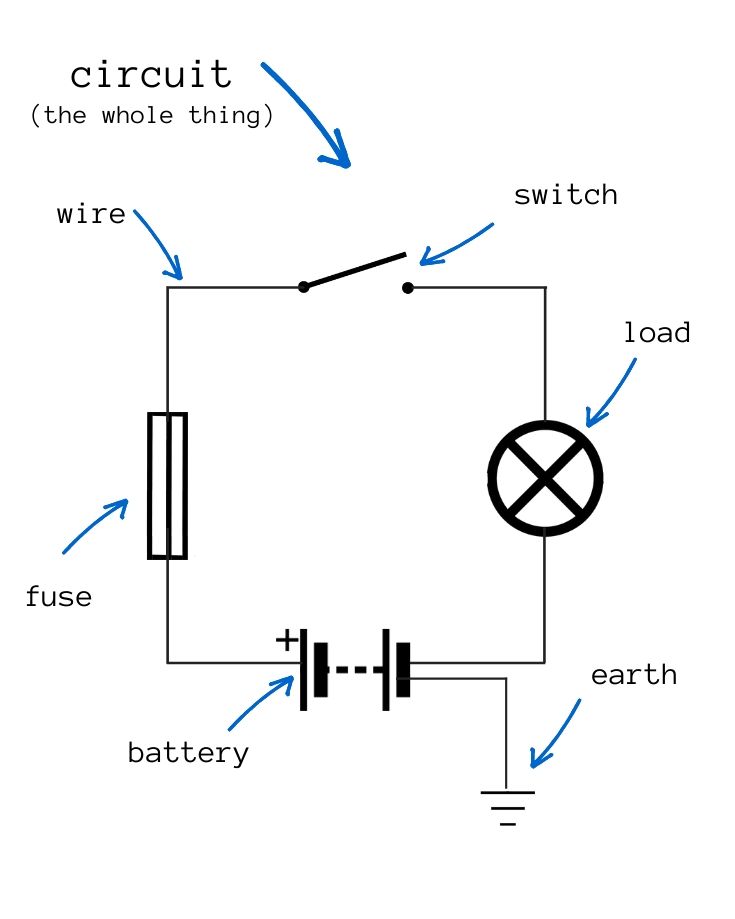
Below, we’ll talk through each component in simple terms.
- Circuit | A circuit is a path or loop through which electricity flows
- Power source | The battery bank provides the electricity
- Connectors or conductors | A connector is what the path is made from, i.e., the wires
- Switches | A switch allows the circuit to be opened and closed. The circuit is complete when the switch is closed and electricity flows.
- Fuse | A small strip of wire that protects components on the circuit in the event of an electrical surge or increase in voltage
- Load | The load refers to the appliances and devices powered by the power source
- Earth | A connection to the ground
Sounds simple enough? We’ll go through each of those in-depth now.
4.1. Electrical Circuits For Your Van
There are basically 2 types of electrical circuits:
- DC circuit
- AC circuit
4.1.1. DC Circuits
Batteries tend to be the main power supply for campervan accessories and appliances.
Because they hold a limited amount of stored energy, it’s best to use them to power low voltage appliances, even when recharged by solar and shore power.
12v appliances are usually lower voltage than their AC alternatives. That’s why your campervan appliances should be 12v wherever possible.
So, most of the circuits you need in your conversion will be DC circuits.
A DC circuit works by supplying power from the battery’s positive terminal to the negative terminal via the appliance.
The power flow stops when the circuit is broken by opening a switch, blowing a fuse, or disconnecting a wire.
4.1.2. AC Circuits
AC circuits run on mains electricity, just like in a house.
They’re engineered to transmit massive voltages & currents, so if not handled properly, they can cause serious injury or even death.
If unsure of your electrical skills, please, please, please seek professional advice.
You must install an AC circuit if you want to charge your campervan batteries from a mains hookup. In addition, you may need to adhere to local & legal regulations.
The simplest campervan AC circuit will have one device: a battery charger.
If going to the effort of installing a battery charger, it’s worth fitting a separate power socket too.
This way, when you’re hooked up, you can power other devices that would typically be a heavy drain on your batteries.
This is especially useful if you want dedicated AC circuits to run appliances like air conditioning units when you’re hooked up to shore power.
4.1.3. Ring Main v Dedicated Circuit
Most campervan’s DC electrical system components should sit on dedicated circuits. Each should have a direct line back to the battery’s negative terminal.
This way, other appliances are unaffected if there’s a failure on the circuit.
There are instances, though, where a ring main could be an acceptable installation.
A ring main is basically a circuit with multiple components.
For example, Christmas tree lights typically sit on a daisy chain ring main.
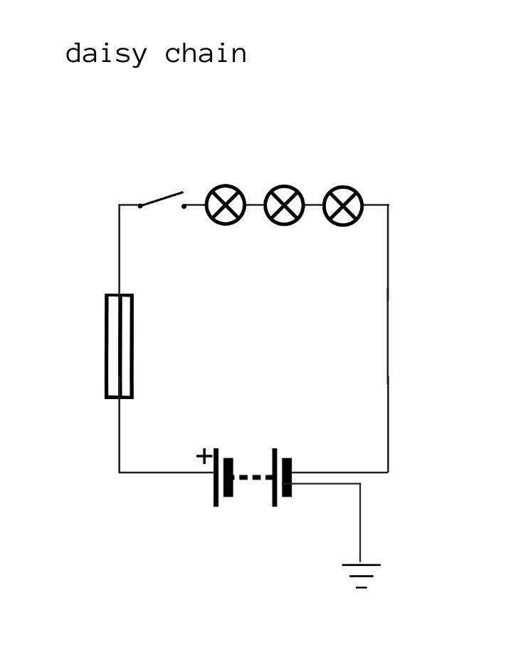
They are fitted in a direct series. The output from one light goes directly to the input of the next, and so on, throughout the entire string of lights.
If one bulb fails, the circuit is broken, and they all fail.
A more common ring main has multiple components spurred off the main ring in parallel. If one component fails, the circuit remains intact, so nothing else is affected.
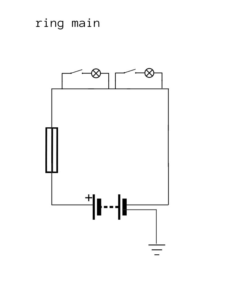
We only recommend ring mains for extremely low current and non-essential services.
For example, our van has 3 12v LED reading lights on a mains ring circuit. Everything else is on a dedicated circuit.
4.1.4. Short Circuits
A short circuit occurs when there’s a breach in the electrical circuit, causing current leakage.
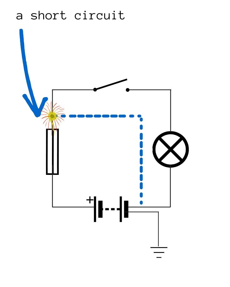
This could be caused by a loose wire or faulty installation.
Electricity takes the path of least resistance to the ground. If that path is through flammable material or a person, the result could be fire, injury, or both.
Short circuits happen from time to time. They can be caused by broken or damaged cables; vibrations may loosen connections or cause wear on the cable’s insulation.
A fuse or circuit breaker will effectively shut the power supply off to minimize the impact of a short circuit.
4.2. Power Source – Campervan Batteries
Deep cycle batteries or 12v leisure batteries are designed to release their energy in a steady flow over a long period.
Leisure batteries can withstand hundreds, if not thousands, of discharges and recharging cycles. That makes them ideal for storing energy for your van’s electrical needs.
Battery technology has been evolving for hundreds of years. These days, we can stream movies on our smartphones, powered by ultra-thin lithium batteries.
Van lifers can enjoy these advancements in technology too.
We’ve written a complete guide to campervan batteries. It covers everything you need to decide on the best battery for your lifestyle. It also includes connecting multiple batteries to create a larger battery bank.
It also highlights how to deal with different battery types and the importance of using compatible components.
4.3. Campervan Wires
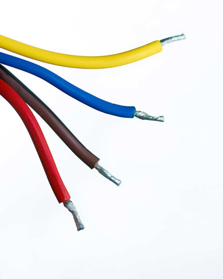
A wire is a flexible strand of metal that conducts electrical energy allowing it to flow from one point to another.
The flow of the electrical energy through a wire is called current, measured in amps. It’s this current that is harmful, even deadly.
When you touch a live wire, you will get an electric shock.
If the wire is on a 240v AC circuit, expect to be blown off your feet and land 6 feet under.
On a DC circuit, injury is still possible, though probably not as severe as the AC supply would inflict.
This hopefully illustrates why you need to take care.
Anyway, back to the case in point.
Wires are covered by a plastic sheath. It protects the wire from damage and any conductive element coming into contact from feeling the adverse effects of the current.
A successful campervan wiring installation depends on:
- sizing wires correctly,
- using the correct type of cable, and
- planning efficient cable runs.
4.3.1. Sizing Campervan Wiring
You must use the correct wire size in your build.
Three factors determine the correct wire size:
- Current
- Circuit length
- Campervan Wiring Regulations
4.3.1.1. Current
Current (amps) pass through the wire – think of it like water through a hose.
If the wire is too small for the amount of current passing through, there will be greater resistance. Then the wire will get hot, possibly melting the sheath and burning the wire.
Without protective fuses or circuit breakers, you don’t want that touching the side of your van! Note the previous warning about injury & death!
The correct wire size allows the current to pass without much resistance or heating.
Using a larger wire than necessary is an even better option. It reduces the chance of cable burnout and makes the electrical circuit more efficient because there’s less resistance.
4.3.1.2. Circuit Length
The total length of the circuit is an important factor in choosing the correct size of campervan wires.
The longer the circuit, the more significant the voltage drop. Anything over 1.8 metres or 6 feet, particularly in low voltage circuits like your van’s 12v system, could suffer as much as a 10% voltage drop.
So, where your battery supplies 12v at the positive terminal, that could be 10% lower by the time it reaches the appliance.
This means your bunk light at the back of your van won’t burn as brightly as the one in the front.
Using a slightly larger cable will help reduce the voltage drop.
Large wires are more power-efficient but more expensive than small wires. So if you use massive wires everywhere, it can become unnecessarily expensive.
4.3.1.3. Campervan Wiring Regulations
Campervan electrical regulations vary from country to country.
In some places, regulations are mandatory, and you may experience restrictions on use unless you adhere to them.
In other places, only guidelines are issued.
Regardless, it’s sensible to have someone check over your DIY campervan build, if only for peace of mind that it’s safe and follows best practice.
In the UK, check guidelines on the British Standards with the Caravan Club. Or, if possible, check the latest 18 edition electrical regulations section 721.
In Canada, RVs need to comply with electrical regulations laid out in each state.
For both the USA and Canada, you can get more information on the RV industry association website.
New Zealand and Australia use these regulations.
4.3.2. How To Calculate The Right Wire Size
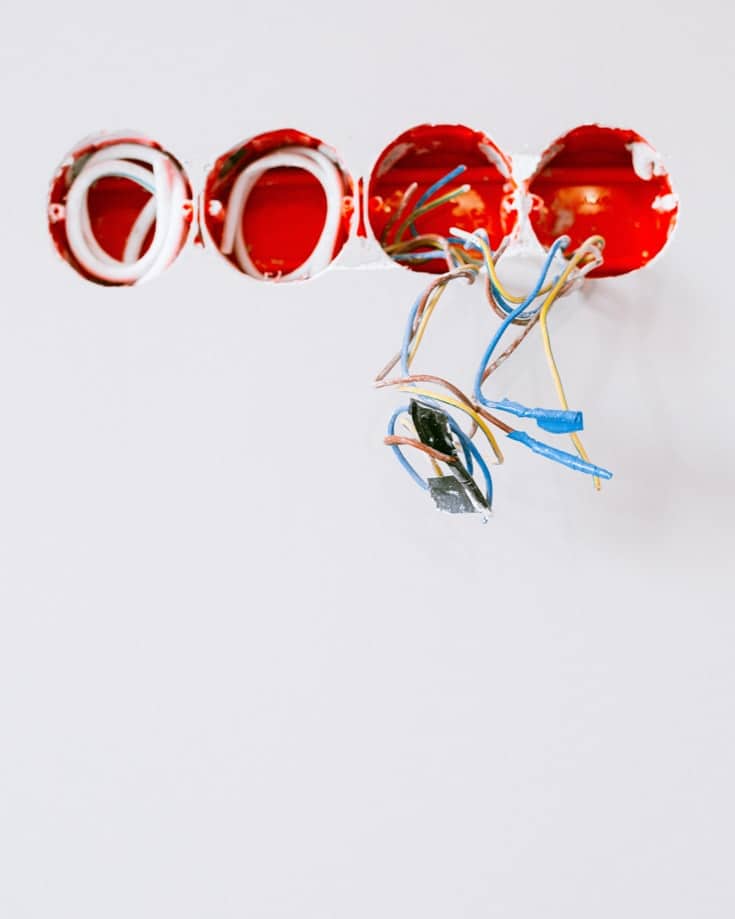
Cable is sold in rolls of dozens of metres, so bulk buying the most appropriate size will help keep your conversion costs down.
Step 1 | Determine the current rating (i.e., amps) for every appliance you expect to use in your campervan.
Some appliances will state their rating as watts rather than amps.
For 12 volt components like your fridge, campervan lights, and USB phone charger, for example, the calculation is:
Amps = Watts / 12 volts
unless you’re running a 24 volt system, you will divide it by 24 instead of 12.
You might plan to use some household appliances that are 110v, 220v, or 240v – like a microwave, TV, or cordless drill battery charger.
You’ll need to use an inverter to convert the battery’s DC power to AC so they can run.
AC power works differently from DC power, so the current calculation is:
Amps = Watts / (Voltage x 0.8)
Step 2 | Determine the length of the longest circuit you plan to install.
To do this, measure the total distance of the cable run. Make sure to measure from the battery to the appliance and back to the battery again.
It’s helpful to use a ball of string to do this, then measure the string length.
Step 3 | Determine the correct wire size.
For a quick estimate, use the table below.
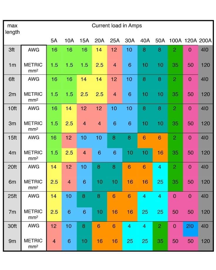
Choose the maximum cable length on the left based on your measurements in step 2 above. Next, choose the amps based on the highest number calculated in step 1 above.
The standards of wire size and current load are defined in the US by the AWG size and in the UK & Europe by a mm metric scale.
The table below shows both measurements.
* We’ve only noted lengths typical for a campervan build.
** The sizes shown will give approx a 3% voltage drop rather than 10% with a smaller cable.
For an accurate calculation of the minimum wire gauge for each circuit, use our online wire size calculator. It also calculates switch and relay sizes too.
4.3.3. Types Of Electrical Cable
Different cables have different purposes, and you need to buy the right type for each aspect of your campervan electrical system.
- For DC circuits, use single core multi-strand cable. These are simple cables with a single wire inside the sheath.
- For AC circuits, use multi-core multi-strand cables with at least 3 cores. These are basically cables within a cable like those attached to a lamp plug.
- Solar panel cable tends to be sold as a specific type; in reality, it’s just 10 AWG/ 6mm² wire.
- Battery to battery links are heavy gauge – so they’re too thick and expensive to use in the entire DC circuit.
4.3.4. Planning Cable Runs In A Campervan
Even a relatively simple electrical setup uses loads of cable. For example, we have over 400 metres of campervan wiring in our Mercedes Sprinter van conversion.
Reducing the length of the cable runs helps to keep costs down, too.
You can see from the table above that a shorter distance needs a lower-rated cable.
The table already accounts for inefficiencies and adds a contingency, so you only need to expect a 3% voltage loss.
Still, aim to keep everything compact and installed as close to each other as possible to minimise cable length and voltage losses.
Lay cables carefully. Avoid sharp corners or areas where the cable may rub and eventually fray.
For belt & braces, fitting conduit to feed the cables through will help avoid these issues.
4.3.5. Cable Colours & Numbering
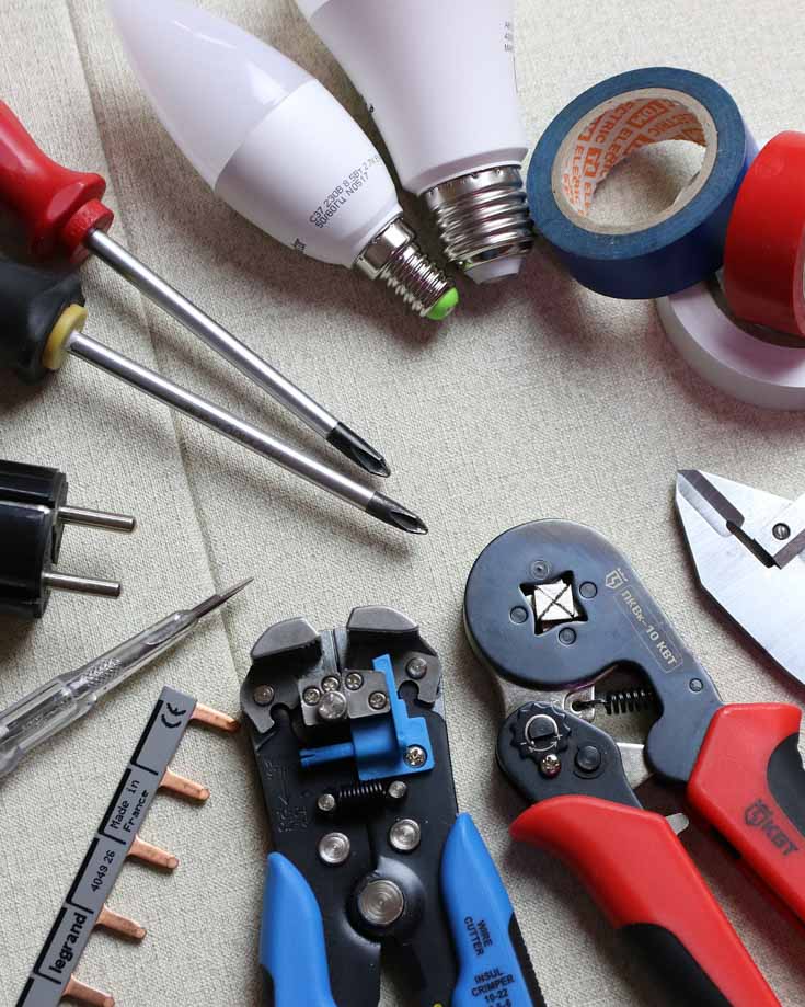
You can buy cable in all sorts of colours. However, we advise sticking to the standard colour convention wherever possible for safety reasons.
For DC circuits:
- Use red cable for the live wire from the battery to the appliance, and
- Use black cable for the negative wire back to the battery.
Sometimes, thicker wires are hard to find in red. In this case, buy black and use red electrical tape or heat shrink to mark each end of the live wire.
The colour coding used in AC circuits for wiring your shore power hookup varies worldwide.
We recommend you fit the standard based on local regulations.
As an example, in the UK and Europe:
- Live is brown
- Neutral is blue and
- Earth is green & yellow
whereas in the USA:
- Live is black or red
- Neutral is white and
- Protect Ground (Earth) is bare (uncovered), green or green & yellow
A more professional approach is to individually number all cables per your design.
When designing your electrical system, place a unique number on each end of the wire in the diagram or schematic.
Use cable numbering collars or tags to identify each wire as you lay it.
This helps when building because it might be several months between laying a cable and installing a component.
You will instantly know its purpose once you read your electrical schematic if it’s numbered.
It also helps in the future if you have to fault find on a circuit.
4.4. Switches, Relays, Fuses & Breakers
Fuses, switches, and relays have different roles within your campervan’s electrical setup.
However, the one thing they all have in common is they break the circuit. So, fundamentally, they control when power is supplied and when it’s not.
- Switches tend to break the circuit for operational purposes. So you flick a switch to turn the lights on, closing the circuit.
- Relays are electrically controlled switches.
- Fuses act as a layer of protection. When they receive an unexpected current, they melt, snap, and break the circuit. The resulting open circuit can do no harm, so it’s a safety device.
- Circuit breakers act as reusable fuses by opening switches. We’ll explain!
4.4.1. Switches
A switch is a mechanical lever that, when operated, opens or closes the electrical contact and stops or starts the electrical supply.
As with all electrical components, switches have an amp rating indicating a safe current at which they can operate.
You can buy switches to handle massive currents, but they get physically bigger and more clunky with a higher rating.
Therefore, it’s essential to understand the current demands of your appliances and get suitably sized switches.
For low current uses below about 10 amps, like your water pump or lights, for example, switches are ideal.
On high current circuits, there’s a risk that the electricity will try to jump or arc across the contacts as they open or close. That’s a dangerous situation for anyone flicking the switch.
In a campervan, there are a few high current scenarios where dinky switches just won’t do the job safely. A couple of examples are:
- Turning on/off the power to or from the batteries directly.
- Operating appliances that may have a current rating too high for a reasonably sized switch. A coalescer water heater is a good example. Ours draws 18 amps.
In such cases, we need either a large switch or a relay.
In our van conversion, we’ve installed 2 big battery disconnect switches. 1 allows us to switch off all incoming charge power from the alternator, solar panels, and 240v battery charger.
The other allows us to isolate the battery from supplying power to any circuit in the van’s living quarters.
So if we were to store the van or ship the van across the Atlantic to South America, we’d isolate everything.
For our coalsecer water heater, we’ve fitted a relay.
4.4.2. Relays
A relay is basically an electromagnetic switch.
A small electric current is sent to the relay by flicking a conventional switch. A coil within the relay becomes magnetic, operating a lever to close the primary circuit.
So with our coalescer water heater, we flick a switch that sends a small current to the relay, closing the high current circuit.
This helps us avoid electrocuting ourselves or having a substantial, ugly switch in the van.
We also use a split charge relay to allow us to charge our leisure batteries from the alternator as we drive.
4.4.3. Fuses
In campervan electrics, every electrical circuit has a fuse on the live side of the circuit.
A fuse is a thin strip of wire in a plastic holder designed to burn out and melt if a current greater than its amp rating passes through.
This breaks the circuit, and the appliance stops working, indicating a problem with the circuit or the component it supplies.
Fuses protect the battery and people from electrical failings in components or circuits.
Always include an appropriate-sized fuse on the live side of the circuit in your design.
For example, your 12v portable fridge might draw 5 amps, and your LED lighting may draw a fraction of an amp.
Put a 5 amp fuse on your fridge (or whatever the manufacturer recommends). A half amp fuse or even smaller is acceptable for the lighting circuit.
Sometimes a fuse fails because there was a blip in the current somewhere, or the fuse failed through age. Replace it, and all is well.
However, suppose it blows again as soon as you replace it or switch on the appliance. In that case, there’s a problem needing further investigation.
It could be a faulty appliance, loose wire, or a short circuit.
Do not insert a larger rated fuse. The system will not be protected; the fault will still exist and will appear somewhere else at some point.
Worst case, the failing component or your battery could be seriously damaged to the point it burns, melts, or catches fire.
The Campervan Electrics Handbook includes a detailed chapter on troubleshooting electrical problems. In addition, it includes easy-to-follow flowcharts.
4.4.4. Circuit Breakers
A circuit breaker is like a mechanical fuse.
When it senses a current greater than its amp rating, it operates, opening the internal contacts like a switch.
This immediately stops the current flowing through the circuit.
Because they’re electro-mechanical, they can be reset like a switch.
It is possible to get circuit breakers for a 12v DC setup. However, because of their relatively high cost compared to fuses, they’re often not used in campervan installations.
Some cheaper products may operate at entirely different thresholds than their labels state. For example, they can trip too early or not at all. For your safety, always use good quality circuit breakers.
Circuit breakers are a mandatory component in AC circuits.
They are essential safety devices and must include a fast-acting Residual Current Device (RCD) to prevent electric shocks.
You have 2 options when buying an RCD for your camper: a single pole or a double pole RCD.
A single-pole stops the power supply from the live cable, while a double-pole RCD stops it from both the live and neutral lines.
The AC RCD breaker will be contained in its own non-conductive container.
We would install a double over a single pole RCD for a campervan.
Even though the trip will operate and the circuit open, a single-pole RCD won’t protect you from electrical contact on the neutral side.
Do not use fuses for any AC installations. Instead, always use an RCD.
If you are not sure, seek the services of a qualified electrician.
4.5. Earth Or Grounding
Electricity is naturally drawn to the lowest voltage point it can find a path.
The largest and lowest voltage point around most of us is the ground. The physical ground upon which we stand.
The battery’s positive terminal has a higher voltage than the negative terminal. So, when we create a circuit, the electrical current moves from the negative terminal toward the positive terminal.
By keeping the negative terminal’s voltage as low as possible, preferably zero, the energy will always flow efficiently away from it. And living in a van full-time, we love an efficient campervan electrical system!
The best way to do this is to attach the battery’s negative terminal to the earth.
Now a campervan sits on at least 4 rubber boots – though we have had Mowgli the Unimog on 2 wheels once!
Anyway, we digress. The rubber boots insulate the van from the earth, so we need to attach the negative terminal to something else.
The next biggest thing around in a campervan is the chassis. So by attaching our earth to the van’s chassis, we keep the voltage at the negative terminal at zero volts.
Perfect for an efficient electrical setup.
Most vehicles are pre-fitted with an earth point. Check with the manufacturer for your make and model to locate it.
In AC circuits, your shore power hook-up should use the earth connection from the main electrical supply. It also needs to be separately connected to the van’s earth point.
When installing your AC circuit, ensure this is connected for your safety.
That said, there are some countries we’ve visited where the local supply wasn’t connected to a proper earth point.
We noticed when we got occasional electrical tingles and minor shocks from the metal parts of the van. Sometimes even from our laptops!
When we’re a bit suspicious, we check the integrity of the supplied earth with a multimeter.
If in doubt, don’t connect.
4.6. Other Installation Components
The installation guide below provides a complete list of tools and materials you need to wire your campervan.
There are a few items on the list worth talking through separately.
4.6.1. Fuse blocks
A camper van conversion can easily have upwards of 20 circuits, each needing a dedicated fuse.
For easy maintenance and replacement, it’s preferable to have all the fuses located together.
A fuse block allows you to hold multiple fuses attached to their circuits in a single location.
A properly mounted fuse block will hold the fuse in place, so they don’t fall out as you drive over bumps in the road.
Some fuse boxes distribute the 12v supply via an internal bus bar.
4.6.2. Bus Bars
Rather than attach every circuit directly to the battery, it’s easier to install a bus bar to the battery.
Each circuit is then attached to the bus bar rather than the battery. That makes maintenance, installation, and future expansion easier.
To choose the correct size fuse box and bus bars:
- count how many circuits you have and
- add up the total current of every circuit you plan to connect (assume everything will be switched on simultaneously).
You need a fuse block and bus bar to handle a current greater than your total. It should also have more fuse holders and terminal connecting points than you have circuits.
They’re not cheap, so it’s best to oversize these components to allow for future expansion.
You can buy a combined fuse block and bus bar for easier installation.
4.6.3. Switch Panels
Given that you might have a few switches for various campervan appliances, a dedicated switch panel will keep things tidy.
There are many types of switch panels on the market.
The more expensive include mini 12v breakers or fuse blocks, volt meters, LED displays to control heaters, fans, TVs, etc.
Less complex panels allow you to modify and insert your own switch types and meters specifically for your build.
4.6.4. Terminals / connectors
You’ll need to attach terminals (or connectors) to most of the wires to install the camper’s electrical components into their circuits.
Connectors come in all shapes and sizes. You need to fit the correct terminal depending on its connected component and wire size.
There are broadly 3 methods of connecting the terminals to the wires:
- Crimping
- Soldering
- Screwed terminals
Which method you choose is down to personal preference. Crimping is cheaper and easier than soldering, but we feel the join is more robust when soldered.
We do use crimping but add a spot of solder to the end of the wire first to make it a little thicker, so the join is tighter.
We’ve not had any failures yet, even with driving thousands of miles of track in South America.
4.6.4.1.Crimping
In camper van builds, most terminals will be crimped connectors with either a metal eye, spay terminal or wire-to-wire joint.
There’s a set of standard sizes of connectors handy to have in your tool kit.
To attach the connectors to the wires, you need a crimping tool.
For large cables, like those you’ll use on your batteries, you’ll need a hydraulic crimping tool to apply enough pressure to attach the crimp.
4.6.4.2. Soldering
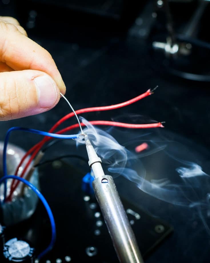
Soldering is the application of melted lead and tin onto a join to create a permanent connection.
This requires a soldering iron and a roll of solder.
A soldering iron is a metal probe that heats up the solder.
They usually run off an AC power supply, but cordless models use butane gas.
The gas models are better for on-the-road repairs.
You don’t need any specialised skills to use a soldering iron, and with a bit of practice, you can achieve neat connections.
Top tip | Make sure each surface is clean before you start so the solder sticks properly.
4.6.4.3. Screwed terminals
This type of connector is a simple hole to insert the wire into and clamp down using a fitted screw or bolt.
You only need to strip a small amount of wire from its sheathing and insert it. Then, tighten with a screwdriver, small spanner, or a spring-loaded clamp, and it’s done.
They make life simple, but sometimes it’s challenging to get the wire into the connector or get a tight grip on the wire. So it is advisable, and in some regions obligatory, to crimp the bare stranded wire end with a pin-style crimp. It is definitely easier!
Screwed terminals are prone to loosening too.
You need a small flat head screwdriver on smaller connections to fix the wires.
4.6.4.4. Heat shrink
Some crimped and soldered terminals don’t have plastic covers, so the bare metal presents a shock hazard.
To cover them, we use heat shrink.
Heat shrink is a plastic tube that, when evenly heated with hot air, reduces in size (shrinks) around the objects it covers.
You need a heat gun and heat shrink tubing to use this method of covering joints. They’re not especially cheap, though.
You could use electrical tape instead, but it doesn’t give a tidy finish, isn’t permanent, waterproof, or as strong.
5. Circuit Commissioning

In the campervan wiring installation guide below, we talk about circuit commissioning. However, we’ll expand on the instructions here to keep the instructions simple.
For safety reasons, you do not want any power flowing through the wires while installing electrical components.
Therefore, never insert the fuse until you’ve thoroughly tested the circuit and are ready to let the power flow.
Once all the components are installed, carry out your safety checks:
- Physically inspect all connections on the circuit.
- Using a multimeter, check the continuity of the entire circuit. Ensure the fuse is out, the return cable is not connected to the negative battery terminal, and the switch is closed.
- Check there’s no short to earth with the multimeter, or better still, use an earth tester if you have one.
- Do not proceed until you’ve satisfied these tests.
- Open the switch (so the component is off).
- Connect the return cable to the negative battery terminal.
- Insert the fuse.
- Open the switch.
- Use the multimeter to check the voltage levels around the entire circuit to make sure there are no higher than expected voltage drops.
Safety Notice
Before we get into the details, electricity is a serious matter.
Done right, you’ll have a safe setup.
Done wrong, it could lead to injury or worse. There’s loads of often conflicting information available on the internet. So do your research well.
We’ve installed our own campervan wiring systems a few times (and even written a book), but we’re not qualified, electricians.
If you’re in any doubt, stop and ask a qualified electrician.
Campervan wiring can quickly grow into a complex installation but by breaking it down to its component parts, we can simplify it for easier understanding.
The guide below describes how to install the 12v DC circuits in a DIY campervan conversion.
We have separate installation guides for camper solar panels, batteries, split charge relays, 12v battery monitoring systems and battery to battery chargers too.
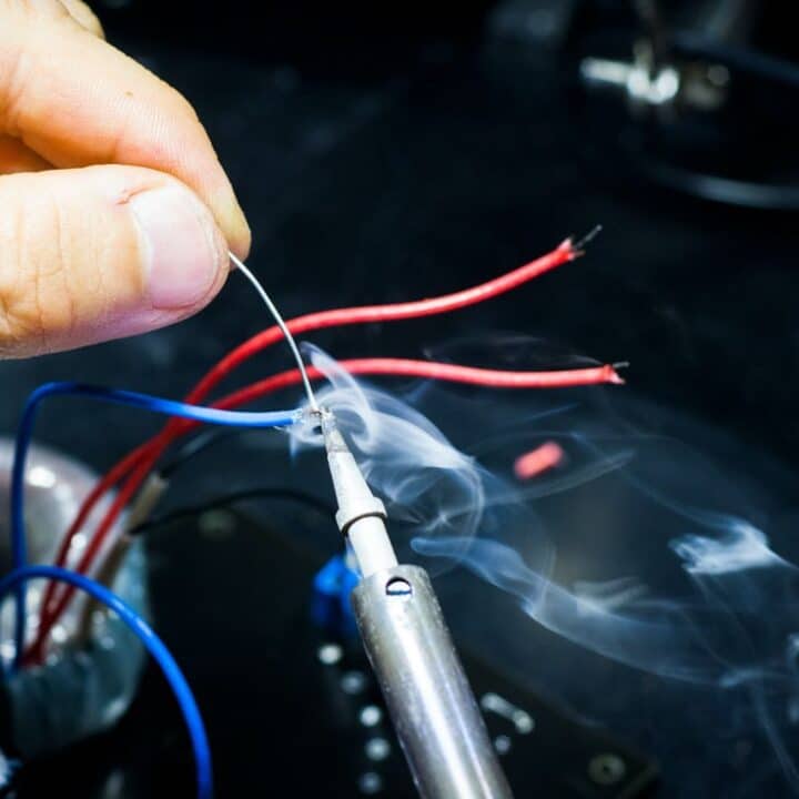
How To Install A 12v DC Campervan Wiring System
A step by step guide to installing a 12v DC wiring system in your campervan including battery, appliances, fuses blocks and bus bars.
Materials
- Cable ties
- Conduit
- Fuse block with combined bus bar
- 1 inline fuse holder
- Bus bar
- Switch panel
- Battery
- Battery tray
- Battery straps
- Braided earth strap
- Bolts
- Cable red & black
- Cable number tags
- Connectors
- Heat shrink tubing
- Solder
- Crimps
- Fuses
- Isolator switch
- Battery terminal connectors
Tools
- Electric screwdriver / drill
- Selection of metal cutting drill bits
- Soldering iron
- Heat gun
- Wire cutter
- Wire stripper
- Multimeter
- Megga earth tester (nice to have)
- Crimping tool
- Pliers
- A selection of screwdrivers and spanners
- Hack saw
Instructions
Pre installation
- Make sure you fully understand your electrical schematic, incorporating everything you need with extra capacity for future expansion
- Make sure you have access to all the tools and materials you need before you start
- Ideally, fit all components in their operating locations before you begin, follow the manufacturer’s instructions. This isn’t essential but it makes our instructions simpler!
- Confirm cable and connectors are planned sizes
- Check the location of your primary earth point closest to where you’ll fit the battery
- If you haven’t already fitted your components, physically mark their locations and identify where the cables will connect. In tight spaces, use a cardboard template to ensure components will fit before you wire it up
- Identify the cable runs between each major component, looking for the shortest, practical route.
Cable installation preparation
- Install conduit, securing it with cable ties where necessary
- Fit fuse panel (without the fuses) to its operating position as per the manufacturer’s instructions
- Fit positive and negative bus bars to their operating positions as per the manufacturer’s instructions
- Install switch panel to its operating position as per the manufacturer’s instructions
Install battery tray & earth point
- Install battery tray so it’s secure, preferably with bolts. You do not want this to come loose in the event of a collision
- If there is no pre-fitted earth point near your battery tray, fit a bolt securely. This is your new earth point.
- Bolt the braided battery strap to the new earth point.
- Bolt the other end of the braided battery strap to a suitable and clean point on chassis. This needs to be a bare metal spot with no paint, dirt or rust.
- Use a multimeter to check connectivity between the new earth point an existing known earth point, confirming correct installation of the new earth point.
Install battery return cable
- Run black cable from component’s install point, through the conduit, along the planned cable route and to negative busbar
- Attach cable number tags to both ends of each cable
- Trim and attach the negative cable to the component’s negative output cable with a connector secured by a crimp, solder or screwed terminal
- Trim and attach the negative cable to the negative bus bar with the appropriate connectors
- Run cable from negative bus bar to the location where the negative battery terminal post will be, attaching cable number tags to both ends
- Trim and attach one end of the cable to the negative bus bar and attach a connector to the other end, ready for connecting to the battery’s negative post later
If you’re in the enviable position of having all your components installed, repeat this section for all of them at the same time. You already have the black wire on hand and appropriate connectors on hand.
You’ve now installed the negative side of the circuit (without the battery).
We’ll move on to the live side now. This time, we work towards the components from the fuse block.
Install cable from combined fuse block/bus bar to switch panel
- Run red cable from the designated fuse bay to the component’s switch on the switch panel
- Attach cable number tags to both ends of the cable
- Trim each end of the cable, attaching it to the fuse bay and switch with connectors
- Install cable from the switch panel to the component
- Run red cable from the switch to the component’s input terminal
- Attach cable number tags to both ends of the cable
- Trim each end of the cable, attaching it to the switch and component’s input terminal with connectors
If the component isn’t already installed, leave excess wire at the component end for contingency.
Check circuit continuity
Now we’ll check we have a correctly installed circuit from the output of the combined fuse block/bus bar to the negative battery terminal post.
- Check all physical connections on the circuit
- Double check the route through so the cables are attached from the correct fuse bay to the correct switch to the correct component to the bus bar terminal
- Close the switch to make the circuit continuous between these 2 points
- Using a multimeter, check circuit continuity from the output of the combined fuse block/bus bar to the negative battery terminal post. There should be a low reading
Check circuit insulation
- Using the Megga earth tester, attach one probe to output of the fuse bay and the other end to the earth point you installed earlier. There should be no reading, indicating a fully insulated circuit.
Install the battery
If your design calls for more than one 12v battery, check our post on campervan batteries about wiring them in parallel. For simplicity of explaining the instructions here, we’ll only fit 1 battery.
This post is only addressing the DC circuits and not how to charge the batteries. For completeness, we’ve included this section about installing the batteries but for more information, take a look at our article on fitting camper solar panels.
- Fit battery isolator for battery outputs to its operating positions. This will allow you to switch off the entire 12v DC circuit once operational
- Install an inline fuse holder between the battery isolator output and the combined fuse block / busbar.
- Connect one inline fuse holder wire to the combined fuse block / busbar
- Connect the other inline fuse holder wire to the output of the battery isolator switch
- Connect the input wire from the battery isolator switch to a positive battery terminal post connector
- Install the battery into battery tray and secure with battery straps
- Connect a cable from the main earth point, attaching a negative battery terminal connector to the other end, ready for connecting to the battery’s negative
- Take a deep breath, have a cup of tea & relax
Power up the 12v DC circuit
You’re about to release power into your new electrical set up.
- Re-check there are no live wires hanging in your circuits, all negative return cables are attached to the battery negative busbar and the correct polarity is set up so positive circuits and negative circuits do not cross
- Turn all switches on the switch panel and the components to their off positions
- Make sure no fuses are installed
- Check the battery isolators are off
- Attach and secure the battery isolator to the positive battery terminal post
- Attach the negative battery connector from the negative bus bar to the negative battery terminal post
- Attach the negative battery connector from earth to the negative battery terminal post
- Turn the battery isolator to the on position
- Assuming you’ve installed everything safely, there won’t be any sudden flashes, bangs or sparks
- If there are, turn your battery isolator switch to the off position, before testing everything again until you find the fault
- Turn the battery isolator to the off position
- Insert fuse into inline fuse holder between the battery positive terminal post and the combine fuse block / busbar.
- Turn the battery isolator to the on position
- Using a multimeter, confirm you have a reading > 12v between fuse block and earth terminal. A lower voltage may indicate low charge battery or loose battery post connections.
Commission each component in turn
You've installed a 12v DC system with power ready to use.
You are now working on a live electrical system. Take the necessary precautions.
Now we’re ready to switch on each component or appliance in turn.
- Select component to be commissioned
- Check the component is switched off at the switch panel and on the appliance
- Switch battery isolator to the off position
- Insert correct size fuse to the designated fuse bay in the combined fuse block /bus bar
- Switch battery isolator to the on position
- Turn component switch(es) to their on positions
- Thoroughly check component functions as expected
- During each commission step listen, look and smell for any electrical failures such as arcing, burning or buzzing noises.
- If there are, switch the component off, remove the fuse, investigate and repair.
- Repeat the commissioning steps for all components in turn
- Well done! You’ve now successfully installed your campervan DC circuits.
Notes
- If you have no electrical experience, seek professional help with your installation
- Avoid routing cables outsider or underneath the vehicle
- Never route 12v DC and 110/240v AC cables in the same cable run or conduit. They must be at least 50mm apart
- The inline fuse amp rating must be sufficiently large to accommodate the total current rating of the circuits running off it
- Battery cables are fairly chunky so use a hack saw to cut these to the appropriate length
- Battery cables with a crimped terminal requires a specialist tool. Pre-made cables are a more simple choice
And that’s it! You now know everything there is to know about campervan wiring. Just remember to use the right tools and resources to help you do the work safely.
If you ever have any questions, don’t hesitate to ask us in the comments section below. We’ll be happy to help.
Graham Bogie

Graham is a seasoned marine electrical engineer with two decades of experience designing customized electrical systems for plant machinery and converting campers and overland vehicles. His expertise has led him to author the reputable Campervan Electrics Handbook and become the chief designer of the RV Wiring Design Tool. As a knowledgeable figure in the field, his YouTube channel, blog, Facebook group, and newsletter, offering electrical advice and product reviews, reach more than a million users each year.



Can you recommend anyone that is for hire to wire a van ?
Hi Nick, it’s probably best to seek out an electrician local to you. Check on any local Facebook groups for any recommendations for one that has camper experience. That’s not essential to be fair – any good electrician should be able to handle 12v DC. Hope this helps.