I based my camper van electrical design on my needs and a few nice to haves too. Planning to live in the van long term, I didn’t want to scrimp on the set up.
Although not impossible to do, I didn’t want to adapt or expand the electric systems while on the road.
I put a lot of effort into sizing the electrical system for the campervan.
I took stock of all the devices I’d travel with and calculated forecast power consumption, added in contingency and then a bit more.
You can check out our complete set of electrical calculators for RVs and campervan conversions to help size your entire solar setup.
Having identified how I’d generate power to keep the batteries topped up, I set about designing the system before getting my hands dirty with the installation.
This article provides you with my campervan vehicle electrical design.
The design is pretty generic so aside from sizing and component specifics, is what most motorhome and camper vans have installed.
If you’re looking for a design for your own van build, this is a great base to start from.
If you’re new to the world of van builds, our self build camper van conversion guide will get you off to a good start.
Before you begin designing your own wiring set up, swat up on the basics of campervan electrics first.
It’ll help you size your system before you get to the detail of design.
Contents
- Camper van electrical design
- Overview of my camper van electrical design
- Fitting Batteries
- Charging batteries
- Monitoring the camper van electrics
- Camper van main battery output
- Camper van leisure battery output
- Installation notes for campervan electrics
- Components used on the camper van electrical installation
- Tools used on the camper van electrical installation
- Some words of caution
Camper van electrical design
The rest of this article provides my camper van electrical design in the following sections:
- An overview of my camper van electrical design
- Monitoring the camper van electrics
- Charging a leisure battery bank
- Camper van main battery output
- Camper van leisure battery output
- Component list
- Tools list.
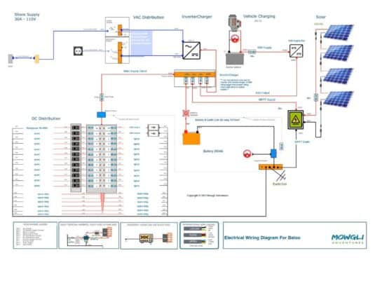
I’ve used simple diagrams to explain my camper van electrical design and circuits. I think they’re easier to read for the less technical readers than professional drawings using electrical conventions.
And I don’t have the correct symbols or software to draw them up anyway.
Overview of my camper van electrical design
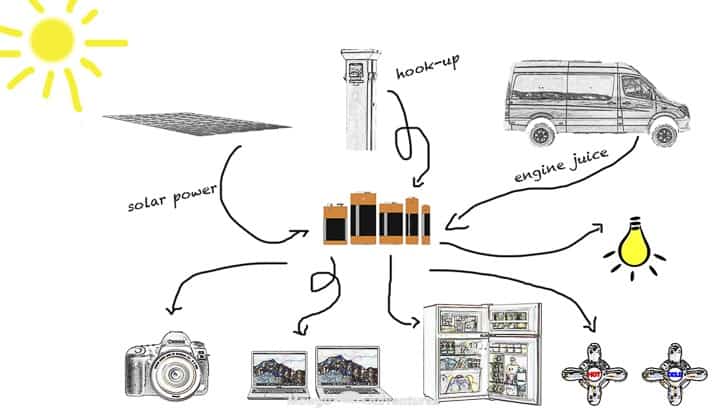
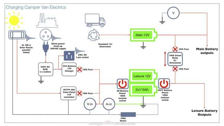
The diagram above outlines in the most simplistic terms, my camper van electrical design.
Using the formula explained here, I calculated I’d need about 80 amp hours (ah) per day including contingency. Assuming the batteries are 50% efficient, I’d need to fit 160ah batteries.
I installed 230ah batteries so have extra contingency too.
I have 3 sources of energy to power up those batteries: shore line, solar and an alternator to store energy from the engine. As far as possible, I’ve installed 12v components including the fridge, cooker, LED lights and the water pump.
I have 12v chargers for most of the portable devices but still have a limited need for 240v sockets, so I’ve fitted a small 300w pure sine wave power inverter.
I’ve heard some professional up fitters have installed 24v or even 48v systems for better power efficiencies. If I’d have gone down this route, I’d have needed to replace my 12v fridge and source all other components.
It proved too difficult trying to source everything I needed in 24v or 48v so stuck with the 12v design.
To monitor the daily performance, usage and available capacity of the camper van electrics, I’ve installed some monitoring equipment too. I have a main control display and a couple of read outs on the dashboard to.
As with any electrical design, the system needs to be protected so any electrical issues don’t cause a catastrophic event like a fire.
To protect the entire camper van electrical system, I’ve installed fuses for every component, battery isolators and a quality RCB for the shore power.
In the event of a faulty component or any electrical issue I can cut off all the electrical power supply, in and out.
Need help & advice with your electrical setup?
Join Our Facebook Support Group
Automatically Create Your Bespoke RV Wiring Diagram
Includes 110v & 240v, solar, B2B, batteries, inverters, 12v, 24v & 48v systems, wire gauges in AWG & mm² & much more!
Fitting camper van batteries
I’ve fitted 2 x 115ah deep cycle gel campervan batteries under the passenger seat and they just about fit. Because I have swivel seats fitted, there’s limited air flow to the batteries.
I’m not expecting any over heating issues but I will keep an eye on them as I travel into hotter conditions. If I experience any issues, I’ll remove the side cowling for more air and/or fit a fan to cool the storage area.
I’ve installed 2 battery isolators so I can switch off all input and output power should I need to. They’re fitted to the side of the passenger seat for quick and easy access too.
Charging camper van batteries
This section details how I’ve designed the camper van electrics to charge the leisure batteries and harness available energy.
Solar power design
Using our campervan solar system to charge camper van batteries is increasing in popularity. Aside from the initial set up cost, energy is harvested free of charge, during daylight hours at least.
I have a 400w solar energy system installed on the camper van.
There’s 4 x 100w flexi panels bonded directly to the roof ribs because I didn’t want to put tracks or roof rails on the roof.
Some people say it’s best to leave a gap of a few centimetres to allow for airflow around them.
I hope the roof ribs provide sufficient air flow though. I’ve not had any issues yet but will keep you posted once I hit hotter climates.
The solar panels are linked in series using EC4 connectors. These are simple bayonet connectors so the design is scalable and I can disconnect any faulty panels easily.
The energy harvested by the solar panels is passed to an MTTP controller, which in turn, converts it to 12v DC to top up the leisure batteries.
I’ve installed a 30 amp fuse between the MTTP controller and the leisure batteries for protection. If the panels prove super efficient in sunnier conditions, I may need to upgrade the fuses to 40 or 50 amps.
You can check out everything you ned to know about camper solar panels in this post, including a complete installation guide and wiring diagrams.
Alternator set up
Charging leisure batteries from the running engine is an efficient source of power. I had a couple of choices: split relay or a separate alternator.
Although a separate alternator offers contingency for charging the main battery, it wasn’t the easiest fit on Baloo.
So I went with the simplest option and installed a smart split charge relay.
My choice of voltage sensitive split charge relay is a common unit. This ingenious component works by monitoring both the main and leisure battery voltage and allows the power to supply either of them.
When the engine is running, the smart relay will channel the energy to the main battery until fully charged. Only then does it redirect the power to the leisure batteries, continuing to monitor the main battery throughout.
Even better, when the engine isn’t running and the solar energy is shining down on the roof, the smart relay monitors the leisure batteries.
When they’re full, the relay allows the excess solar power to supply the main battery. It works in the same way with shore power too.
I’ve installed the relay in the engine bay and a 50 amp fuse on either side of it to protect both the leisure batteries and the main battery from any power surges. It’s working well so far.
Some manufacturers are now fitting their new vehicles with the smart charging capability installed as the standard. I don’t think my smart relay set up will work as designed on these.
I’ve not had the opportunity to play with this yet so not sure what design changes I’d make if Baloo was a younger model.
Shore power design
In addition to charging the leisure batteries from the engine and solar energy, I also have a hook up facility. The shore cable connects to the RCB.
The RCB I installed has 2 breakers; 1 for a 3 pin 240v socket for charging 240v devices and another to power the batteries, via the leisure battery charger.
If you’ve not read the article explaining camper van electrics, (and you should), the battery charger converts 240v AC to 12v DC energy the leisure batteries need.
Although the battery charger already has an integral fuse, for belt and braces I’ve installed another 20 amp fuse between the battery charger and the leisure batteries.
For easy access, I installed the RCB unit under the sofa and the leisure battery charger under the driver’s seat.
I’ve used the hook up facility a lot during the conversion. In fact, the van was connected to the house mains power for about 8 months, almost non-stop.
I’ve not yet needed to use it whilst travelling, as I’ve always had enough energy from the engine or solar but packed the shore cable, just in case.
Monitoring the camper van electrics
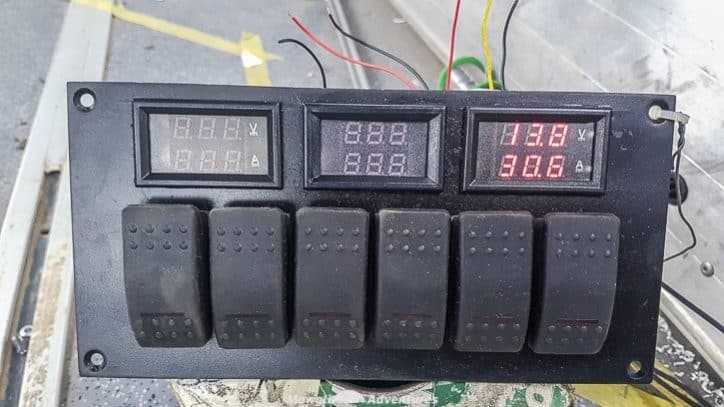
To monitor the daily performance, usage and available capacity of the camper van electrical design, I’ve installed some monitoring equipment too. I have a read out of:
- main battery voltage
- leisure battery voltage
- net current in ammeter
- net current out ammeter
- 12v ring main voltage
- 2nd fuel tank level
- water level gauge
- fridge temperature
- cabin temperature.
As a point of note, I chose off the shelf combined volt and current meters. There are more intelligent monitoring units on the market but they were a little over the top for me. I’m only keen to measure the net current usage.
In the following sections, you’ll see the design components associated with the monitoring set up and I’ll explain them as I walk you through them.
Monitoring incoming power in a camper van
I want to know how much available power I have to use while I’m travelling and it’s especially important for living off-grid.
Knowing all the sources of power are working as expected is critical.
I don’t want to pull up for a planned weekend off-grid and find the split relay hadn’t charged the batteries for the past 300 km.
Measure main battery voltage
I’ve installed a voltmeter on the main battery with a display on the dashboard. When I’m driving, it should read around 13.7v so anything different to this, is an indication of a problem.
When the engine isn’t running, it sits around 12.4v. The display is always switched on so I monitor it when I’m off grid for a few days so I don’t end up with a flat main battery.
Measure leisure battery voltage
I’ve installed a voltmeter on the leisure batteries with a display on the cabin control panel.
This measures the volts supplied to the leisure batteries from which ever source is providing the highest voltage.
The display is always on, it’s situated by the sliding door so I can monitor it regularly throughout the day.
Measure the health of the leisure batteries
I’ve installed an ammeter and a 50 ohm shunt resistor between the battery negative terminal and the earth point to measure how much current the leisure batteries are taking to charge.
This helps me cut back at times of low supply and charge any power heavy devices at times of plenty.
Camper van main battery output
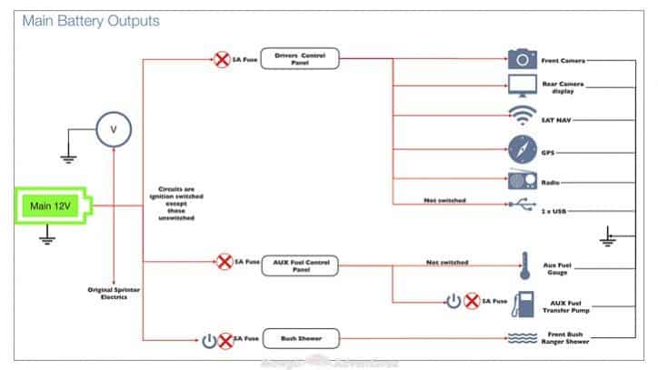
In keeping with my philosophy of not modifying the stock vehicle, I kept additional electrical load away from the main battery as much as possible.
I’ve put 3 fuses into this part of the camper van electrical design to simplify installation and give protection with the smallest fuses.
There are 9 devices/components in total.
5 of them are driving related: GPS, Sat Nav, radio, rear camera and dash cam. Each of these are connected so they only power up when the engine is running to avoid inadvertently leaving a device switched on and ending up with a flat main battery.
I’ve installed 2 USB ports to run off the main battery too but not on a switch so they’re permanently on. I only use these when driving but if I do forget to unplug anything, the main battery display reminds me.
I’ve also installed a 2nd fuel tank gauge without a switch. I run my heating and diesel cooker off this tank so it’s important to know the level. It’s a simple LED gauge and takes almost no current.
The 2nd fuel tank is separated from the main tank by a valve and transfer pump. I’ve installed a switch on this to refill the tank on demand.
I’ve fitted a Bushranger shower (luxury item!). The engine needs to run for this to heat the water so I’ve run it off the main battery for simplicity. Again, this has a switch for obvious reasons.
Camper van leisure battery output
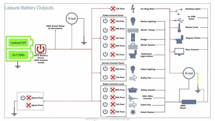
This section is what it’s all about. What lights I have, the devices I plug in, heating and ventilation, right down to how I cook and in my case, even poop!
The devices and utilities in the camper van all (mostly) draw their power from the leisure batteries. If I’ve done my calculations correctly, I can run it all and support the van life I aimed for.
In the diagram above, I’ve indicated the output to the smart relay and the isolator from the leisure batteries, as explained a little earlier.
The remainder of the diagram shows the set up of the output components. Cabling is run between the leisure batteries, fuses, switches and components as detailed above.
The system breaks out into 4 switch areas:
- Cabin control panel
- Drivers control panel
- Local cabin controls
- 12v ring.
Cabin control panel
This control panel houses some of the monitoring displays (more on that in a moment) and 6 carling switches. The switches operate:
- Water Pump
- Fridge power supply
- Kitchen spot lights
- Water heater
- Spare
- Bathroom light & fan.
Every component running off these switches has its own dedicated fuse.
Driver’s control panel
When I bought my campervan she was a minibus and already had cabin lights and a ceiling fan fitted.
When Baloo was a minibus, the lights and the ceiling fan were operated by the minibus driver from the driver’s control panel in the dashboard.
So there was no need to change things unnecessarily.
Although I reconfigured both to run from the leisure batteries rather than the main batteries, there was no real need to move the switches. So they stayed put.
It’s not the most practical thing to have the switch for the kitchen extractor fan in the driver’s control panel. The living space is only a little over 4 metres long, so it’s not too far to walk.
Local cabin controls
Some services have their own dedicated control switches, integrated as part of the component and provided by the manufacturer. In my build, these are:
- Air heater
- Diesel cooker
- Ventilation fan
- 300 watt inverter
12v Ring
There are some systems that don’t need a separate control switch because their power consumption and/or usage is so low. I’ve installed the following components directly on the leisure battery via a shared fuse:
- 12v fan for the campervan composting toilet
- 4 USB sockets
- reversing camera
- water level gauge
I’ve also installed 3 LED reading lights. They each have their own switch and they’re tapped off the 12v ring too.
Installation notes for campervan electrics
I spent 2500 hours over 8 months converting Baloo from a minibus into a fully kitted out camper van.
For loads of helpful articles on how you can build your own camper van, make sure to check out the camper van conversion guide here.
Running electrical cables in the camper van
Some people say campervan wiring should be run after the panelling is complete. This way any cable failures are easier to fix. However, a cable failure is highly unlikely if it’s laid correctly in the first place.
If a cable is laid so it rubs on a corner or is crimped, over time it will fail. By laying them carefully, taping them in place away from sharp corners and protecting them with conduit when necessary, cable failures can be avoided.
So installing the electrics on my camper van was one of the first jobs to be done. 400 metres of cable and it’s all hidden behind the panelling.
Whilst this is neat and tidy, it does reinforce the need for a well thought out camper van design before you start.
This way, you’ll know exactly where you need cables to come out of the panelling to connect to the services some time after they’ve been laid.
Of course, good ideas clubs are best avoided once the panelling is fitted because changes to the location of services may require significant rework.
How I installed the electrics
To give an idea of the process I followed, this is how I installed the electrics in my camper van.
This isn’t an installation guide but a high level overview for illustrative purposes only.
- Fitted batteries and isolators under passenger seat
- Installed:
- fuse panels, shunts and earth point under driver’s seat
- shore power
- smart relay
- solar panels
- system monitoring
- For each component:
- Laid wires from fuse panel to location
- Installed component
- Install fuse
- Switched it on
- Job done.
As each wire was laid for a component, I labelled them so I knew weeks or even months later, what component it was for.
I also commissioned each component in turn, monitoring for faults, shorts or excessive current draws and voltage drops as I went.
I also laid a couple of extra cables for any potential future needs. I’ve already used one of them!
For simplicity and cost saving, I only used 2 wire sizes:
- thin wall cable 28/0.30, 2.0mm², 25.0A – cable OD 2.7mm. Burst capacity to 60A for 30mins and
- thick walled Solar Cable, 60A – 6mm² cable OD 10mm. Burst to 100A for 30 mins.
I installed the smallest fuse rating I could for each component and battery isolators for both charging and discharging circuits.
Components used on the camper van electrical installation
You can find all the electrical components I used on the high street. They’re all marine grade construction.
- Automatic Multi-Stage Leisure Battery Charger – 12V 25A
- Shore power cable
- Voltage Sensitive Split Charge Relay – 12V 140A
- 400w solar panels and controller
- Batteries
- Isolator switches
- Fuse board
- Thin Wall Cable 28/0.30, 2.0mm², 25.0A
- Thick walled Solar Cable, 60A – 6mm²
- Battery monitoring
Tools used on the camper van electrical installation
I didn’t use many specialised tools to install the electrics in the camper van.
If you plan to install the electrical systems in your camper van yourself, you’ll need at least these tools:
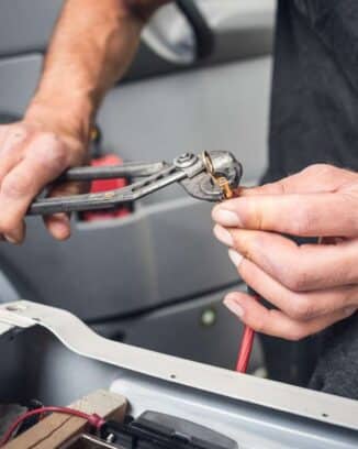
- a good pair of wire cutters
- a good pair of wire strippers
- crimping pliers
- soldering iron
- heat shrink
- cross head and flat head screwdrivers
- multimeter
- kettle.
Some words of caution
This camper van electrical design is what I’ve installed in Baloo.
I’m not a qualified auto electrician, so if you use this as a basis for your own build, please make sure your carry out the necessary safety checks yourself.
Installing electrics in a camper van isn’t a task for someone with no experience.
You don’t need to be a qualified electrician either but some experience will keep you and your camper van safe during the installation and while you’re living in a van.
If in any doubt, get a qualified auto electrician to look over your designs and install or consider outsourcing the job.
This camper van electrical design is specific to my needs. Your own may be similar, or a world apart. The basic principles of the design however, are fundamentally the same.
Graham Bogie

Graham is a seasoned marine electrical engineer with two decades of experience designing customized electrical systems for plant machinery and converting campers and overland vehicles. His expertise has led him to author the reputable Campervan Electrics Handbook and become the chief designer of the RV Wiring Design Tool. As a knowledgeable figure in the field, his YouTube channel, blog, Facebook group, and newsletter, offering electrical advice and product reviews, reach more than a million users each year.

Hi:
as always, another great article, but I wish the photos could be enlarged.
Greetings.
Hi, with regards to shore power, how have you coped with the different voltages between the different countries? Do you have some kind of adaptor to allow you to use the hook up in other countries that you have visited? Thank you :)
Hi Debbie. Yes we have a 110/220v transformer and a range of different adaptors for the various sockets. We’ve only needed the transformer in Brazil so far.
Same question as Nora. Almost a year on. Are the close fitting panels still doing well?
Hi Ash – your timing is impeccable. We recently had to change them after they failed so we wouldn’t now recommend them at all. This post gives our review after a year full-time living in the converted van https://mowgli-adventures.com/sprinter-camper-van-conversion-review/ Give us a shout if you have any questions :-)
What do V, A, V-in, A-in, V-out, A-out refer to?
hi, this is brilliant thank you. one thing you didnt list in your components was and RCB for the hookup.. be grateful for a link.
How have those flexible solar panels worked out for you so far? We are planning to go this route and it would be great to hear if they stood the test of time.
Hi Nora – sorry it’s taken so long to reply. So far the solar panels are performing well. We’ve only been travelling full time with them for a coulee of months and the weather hasn’t been really hot so we need to run for another 6 months before we could say with more confidence. We love the love profile though!